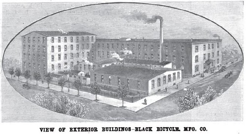
The Black Bicycle Mfg. Co. in 1896, external view
The January 4 1896 issue of Scientific American has illustrations showing scenes from the Black Bicycle Manufacturing Company factory and some description of the manufacturing process in an accompanying article.
THE TRIBUNE BICYCLEWhat I have done here is bring together the illustrations that were on the cover of the issue and with the article with my hand-corrected version of the OCR'ed text, but some errors likely remain (alas) - if you come across a mistake, let me know in the comments and I'll fix. Thanks!!
Within the past three years, the American bicycle Industry has grown up to dimensions which fairly entitle it to be considered representative of the country and of the day. Every day sees hundreds of wheels of high and low grade made in the factories of this country for the American and foreign market. Three years ago the English bicycle was considered by many the best wheel, and the possessor of such was apt to consider himself better equipped than his friend who rode one of American manufacture. Now, all is changed. A visitor to England or to the Continent, if a cycling enthusiast, cannot fail to be impressed by the superiority of American wheels as contrasted with the foreign ones, and no wheelman really an fait in his subject would dream of buying his wheel abroad, so superior is the American make. The industry has brought about an enormous development in the manufacture of special tools and of parts of bicycles.
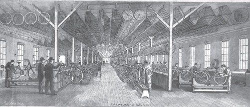
Assembling the Bicycles
Many assumed bicycle manufacturers simply buy these parts and do their own assembling. But for the production of the absolutely high grade American bicycle, a factory is required which will turn out practically all the parts of the wheel manufactured, for unless such is done one concern cannot be answerable for the perfection of the whole machine.
We select as the representative of such a factory the works of the Black Manufacturing Company, of Erie, Pa., a company which produce the highest grade of wheel and which put it on the market purely on its merits without the adventitious advertisement of paid riders. The wheel made by this company, the "Tribune Bicycle," embodies the best possible practice and is correspondingly free from structural variations of unproved merit.
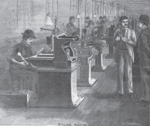
Milling Machine
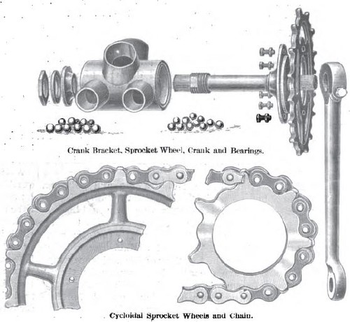
The tubing, whose walls are of 20 gage thickness, is of American make, the company having found that English tubing could not be obtained of sufficiently even quality. At the junctions of the tubes forged connections are employed. These are received in a solid state and are machined out, drilled and turned, until only a shell of the original material is left. Each connection has projecting nipples which enter the ends of the tubes, and the whole is so accurately made that when the ends of the tubes are placed over the nipples the frame will hold itself together without further fastening. The tubes are of uniform diameter throughout and are simply cut of proper length, so that their natural strength is unaffected. The most striking instance of the preparation of the forged connections is in the crank bracket. This is received as a massive forging weighing 3 pounds 2 1/2 ounces, in general shape a cylinder, with four solid projections. This is put into the finishing machine and finished. It comes out with the solid cylinder drilled out so as to present a large aperture through which the crank shaft is to go. and its ends faced off and finished for the reception of the ball races: The four projecting nipples are drilled out and are also turned down on the outside so as to fit accurately the outside of the tubing. The bracket now weighs 8 ounces; all the rest has been converted into drill chips. One of the typical connections is that used for the head of the rear forks, which forging we specially illustrate, in order to show how solid a construction is given to this vital point.
Rear Fork
The frame has now to he brazed together. The pieces are placed in a massive iron jig or template, adapted to receive them and retain them in position, and which holds horizontally the entire frame. This template is mathematically accurate. While held therein, holes are drilled through the connections and tube ends and pins are driven in, pinning all the parts together. When removed from the jig the frame is perfectly rigid. It now goes to the braziers, who, with the best quality of brass and with large gas blowpipes, braze all the the liquid spelter penetrating all the join even running out around the pins. The frame next goes to the filers, after the borax has been brushed off it, who with file and emery paper, go over all the connections and over the tubing, polishing it all, and removing every excrescence, which, it will be observed, gives the frame an absolute hand finish over all its surface.
Brazing Room
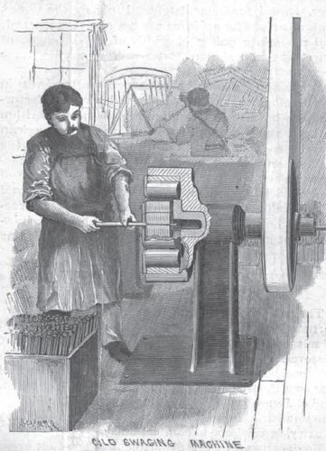
The forks taper toward the end, and to produce this taper cold swedging is employed. The swedging machine carries a heavy head like a lathe head or chuck, which rotates in a horizontal axis, and within which are eight hammers, which by the action of the machine move in and out in radial directions. A piece of cold tubing pushed into the machine and fed up by hand is subjected to a multiplicity of blows and has its diameter rapidly reduced, the workman being able to give it any desired taper. The metal thus tapered is flattened and bent to the proper curve to give one side of the fork.
Cold Swaging Machine
[For someone who doesn't know what "swaging" is - like me - you can read something about it in Wikipedia.]
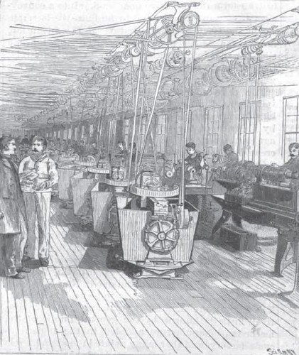
The cups and cones for the ball bearings are made on automatic turret lathes, the turret carrying in some cases as many as five tools. A bar of tool steel which may be 20 feet long is introduced into the machine and is gradually and automatically fed up to the tools, which shape and cut off from it bearing after bearing, which drop from it every few seconds without any attention from the workman. A liberal supply of oil is kept in constant circulation through the machine, falling upon the cutting tools. The bearings thus finished are purposely left 0 005 of an inch too large. They are then screwed on a mandrel in a special lathe and the final finish is given by hand. They are then tempered by secret process with sperm oil and polished, coming out with a beautiful straw color, equal in finish to any steel tools made. The standard finish of the machine is black enamel and nickel plate. The enamel is put on in four coats, two of India rubber enamel and two polishing coats, the frame being rubbed down with rottenstone between the applications. This gives a finish equal to a piano body. To secure evenness the enamel is applied by dipping in a tank of the compound, after which the parts are hung up and allowed to drip to remove the surplus before baking. All nickel plated parts are first copper plated. This prevents water or moisture from getting under the nickel and rusting the steel and thereby causing a separation of the coating.
[Factory Floor]
The aim of the constructor of this typical American wheel has been to secure simplicity and produce an absolutely standard article. Its criterion is its quality pure and simple. There are, however, some novelties introduced that are especially worthy of illustration. One of these affects the crank and crank shaft mechanism, the crank being secured to the shaft in a new way. V-shaped teeth are formed upon the crank shaft and upon the aperture in the pedal arm. This aperture in the pedal arm is split and provided with a tightening screw. To attach the ciank arm to the shaft, it is thrust over the end of the shaft and the tightening screw is turned up, when it is secured as rigidly as if all were one piece of metal. Those who have struggled with the old-fashioned cotter will realize the advantage of this crank, which is instantly released with two or three turns of a screw.
The handle bar is made adjustable by an arrangement of equal simplicity and efficiency. The socket in the head which receives it is threaded. On the center of the handle bar is brazed a sleeve threaded with the same pitch of screw. The socket is split and provided with a tightening screw. The screw is loosened, the handle bar thrust through the socket and screwed into place. When at the desired angle the screw is tightened and the whole becomes practically one piece of metal. By reversing the handle bars, they can be used in up-tumed or downturned position.
The sprocket wheels ought not to be spoken of as a novelty now. They are cut to the cycloidal or theoretically correct curve, which avoids all friction of the chain against the teeth. This has long been the specialty of the Black Manufacturing Company, but now the system has spread among other companies, and cycloidal sprockets are characteristic of several other first-class wheels.
Cycloidal Sprocket
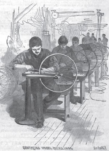
We also illustrate the system of truing up the wheel. Each wheel is mounted on a gaging frame, and the workman, by setting up and loosening the nipples, brings the rim into an absolutely perfect plane. The steering arrangement of the tandem machine deserves attention. Sprockets are carried by the front and rear steering posts, and these sprockets are connected by chains and rods so as to insure unity of steering action between the front and rear handle bars.
Wheel bearings


We are providing industrial-grade heavy duty trolley wheels and reliable heavy duty casters for all applications.
ReplyDelete